VVTi / VTC configuration
| Vehicle | Cams Controlled | Voltage | Frequency Range (Performance Setups) | Base Duty Cycle |
|---|---|---|---|---|
| Audi S4 (2010-2016) | Intake & Exhaust | 12V | 200-300Hz PWM | 0-100% variable (50% hold typical) |
| BMW 335i (2007-2013) | Intake & Exhaust | 12V | 200-300Hz PWM | 50% hold typical |
| Chevy LS (Gen IV, 2007-2015 VVT) | Single cam (pushrod) | 12V | 200-300Hz PWM | 50% hold typical |
| Ford Mustang (2011+ Coyote) | Intake & Exhaust (4 cams) | 12V | 200-300Hz PWM | Higher for retard (50% hold typical) |
| Honda Accord (2003-2007 2.4L VTEC) | Intake | 12V | 200-300Hz PWM | 50% hold typical |
| Honda Accord (2008-2012 3.5L VCM) | Intake (all cams) | 12V | 200-300Hz PWM | 50% hold typical |
| Honda Civic (2006+ iVTEC) | Intake (VVT) + both (lift) | 12V | 200-500Hz PWM | 50% hold typical |
| Honda Fit (2009-2013) | Intake | 12V | 200-500Hz PWM | 50% hold typical |
| Honda S2000 (2000-2009) | Both (lift only) | 12V | N/A (switched on/off) | 0/100% (on/off) |
| Lexus IS300/SC300 (1998-2005) | Intake | 12V | 250-300Hz PWM | 50% hold |
| Mazda Miata (NB2, 2001-2005) | Intake | 12V | 250-285Hz PWM | 30-45% (hold/move) |
| Mitsubishi Evo X (2008+) | Intake & Exhaust | 12V | 300-306Hz PWM | 50% hold typical |
| Nissan 240SX (S14 KA24DE, 1995-1998) | Intake | 12V | 250-300Hz PWM | 50% hold |
| Nissan 350Z/370Z (2003-2018) | Intake | 12V | 250-300Hz PWM | 50% hold |
| Nissan G35 (2003-2008 VQ35DE) | Intake | 12V | 250-300Hz PWM | 50% hold |
| Nissan GT-R (R35, 2009+ VR38DETT) | Intake & Exhaust | 12V | 250-300Hz PWM | 50% hold |
| Nissan Silvia/240SX (S13/S14/S15 SR20DET, 1989-2002) | Intake | 12V | 250-300Hz PWM | 50% hold (or 0/100%) |
| Nissan Skyline (R33/R34 RB25DET NEO, 1993-2002) | Intake | 12V | 250-300Hz PWM | 50% hold |
| Subaru WRX (2004+) | Intake (single) or both (dual AVCS) | 12V | 150-300Hz PWM | 50% hold typical |
| Toyota Celica (2000-2005 VVTi) | Intake | 12V | 250Hz PWM | ~50% hold |
| Toyota FR-S (2013-2016) | Intake & Exhaust | 12V | 150-300Hz PWM | 50% hold typical |
| Toyota MR2 (2000-2005) | Intake | 12V | 250Hz PWM | 37% at idle |
| Toyota Supra (1998-2002 JDM VVTi) | Intake | 12V | 250Hz PWM | ~50% hold |
| VW Golf (2018-2019) | Intake & Exhaust | 12V | 200-300Hz PWM | 50% hold typical |
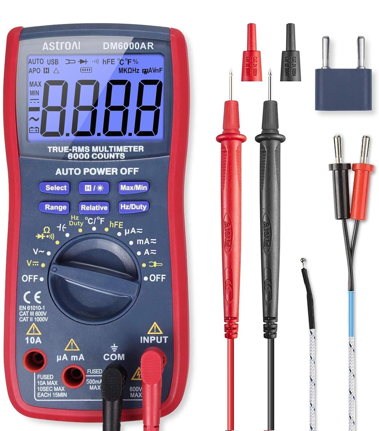
AstroAI Digital Multimeter and Analyzer TRMS 6000 Counts Volt Meter Ohmmeter Auto-Ranging Tester; Accurately Measures Voltage Current Resistance Diodes Continuity Duty-Cycle Capacitance Temperature
Buy on Amazon As an Amazon Associate I earn from qualifying purchases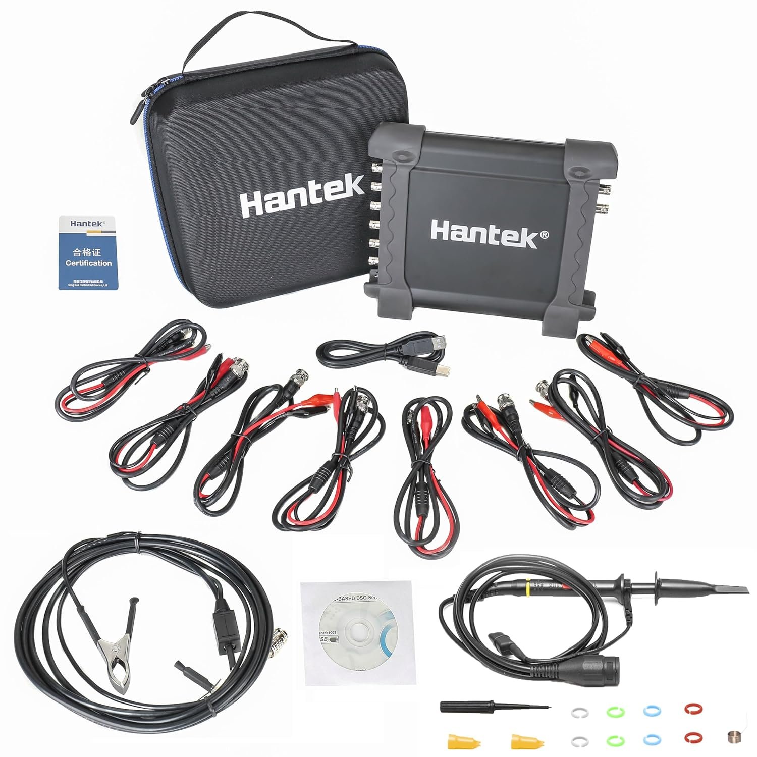
Hantek 1008C PC USB 8CH Automotive Diagnostic Digital Oscilloscope/DAQ/Programmable Generator
Buy on Amazon As an Amazon Associate I earn from qualifying purchases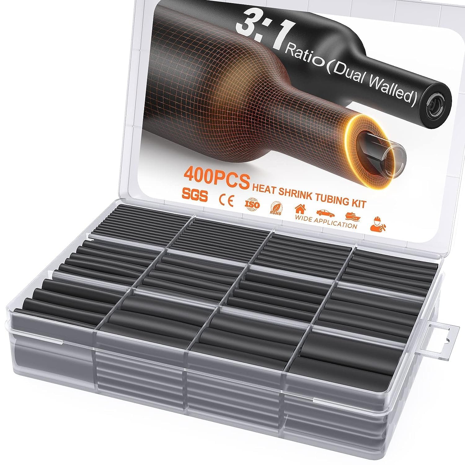
400 Pcs Heat Shrink Tubing Kit-3:1 Ratio Adhesive Lined,Marine Grade Shrink Wrap - Industrial Heat-Shrink Tubing - Black
Buy on Amazon As an Amazon Associate I earn from qualifying purchases
SVAAR 380PCS Non Insulated Butt Connectors Kit Butt Splice Connector Uninsulated Wire Splice Connectors for 26 to 6 Gauge Wire Marine Grade Tinned Copper Seamless Barrel Crimp Butt Splice Terminals
Buy on Amazon As an Amazon Associate I earn from qualifying purchases
3M Scotch Super 33+ Vinyl Electrical Tape, .75-Inch by 66-Feet
Buy on Amazon As an Amazon Associate I earn from qualifying purchases
AstroAI Digital Multimeter and Analyzer TRMS 6000 Counts Volt Meter Ohmmeter Auto-Ranging Tester; Accurately Measures Voltage Current Resistance Diodes Continuity Duty-Cycle Capacitance Temperature
Buy on Amazon As an Amazon Associate I earn from qualifying purchases
Hantek 1008C PC USB 8CH Automotive Diagnostic Digital Oscilloscope/DAQ/Programmable Generator
Buy on Amazon As an Amazon Associate I earn from qualifying purchases
400 Pcs Heat Shrink Tubing Kit-3:1 Ratio Adhesive Lined,Marine Grade Shrink Wrap - Industrial Heat-Shrink Tubing - Black
Buy on Amazon As an Amazon Associate I earn from qualifying purchases
SVAAR 380PCS Non Insulated Butt Connectors Kit Butt Splice Connector Uninsulated Wire Splice Connectors for 26 to 6 Gauge Wire Marine Grade Tinned Copper Seamless Barrel Crimp Butt Splice Terminals
Buy on Amazon As an Amazon Associate I earn from qualifying purchases
3M Scotch Super 33+ Vinyl Electrical Tape, .75-Inch by 66-Feet
Buy on Amazon As an Amazon Associate I earn from qualifying purchasesAdjusting cam angle safely when road tuning
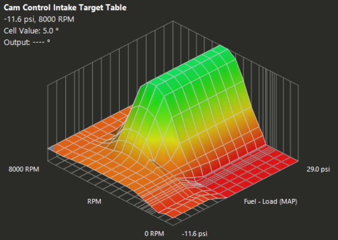
The adjacent picture shows my cam angle chart, and this was built via a street/road tune. I need to rent dyno time and put my car on the dyno, but until then I'm running this.
There's no real way to know what your ideal cam angle is unless you put the car on a dyno. I started with the basemap that Haltech provides, and I increased the fuel amount before I increased cam angle in small increments.
The angles I chose are all just theoretical based on how much airflow I think the engine should have at that RPM. The increased fuel amount is so I don't make the engine run lean as the angle increases. Then as I drive the car, the "Long Term Fuel Trim" fine-tunes the air-to-fuel ratio for me. I just need to apply the changes routinely.
Why does the engine go lean when cam angle is higher? The greater the cam angle, the more airflow into the engine at that RPM, so this changes the air going into the engine, but the fuel amount is predetermined in the fuel table.
How is a dyno better?
It allows you to monitor the power output from the car while you're holding RPM steady. To determine the best ideal cam angle you will:
- Increase fuel on your fuel map a little first at the RPM and boost you're holding steady at
- Then increase cam angle, and watch power level go up or down
- If power output drops, then move your cam angle in the other direction
- After every new angle, make sure AFR is on target
- Make small adjustments to the timing map while still watching power output
Repeat this same process for the areas where the car is commonly driven.
• Start with Haltech basemap → increase fuel first, then cam angle in small steps
• Angles are theoretical (estimated airflow at each RPM)
• Extra fuel prevents lean condition as more air enters with higher angle
• Long Term Fuel Trim helps correct AFR during road driving
• Dyno is far superior: hold steady RPM/boost → adjust angle → watch power
• Always verify AFR after angle changes, then fine-tune timing
• Wrong cam angle → lost power, poor response, or unsafe lean conditions
Dyno method → safest & most accurate way to find true optimal cam angles.
cam angle fuel correction table
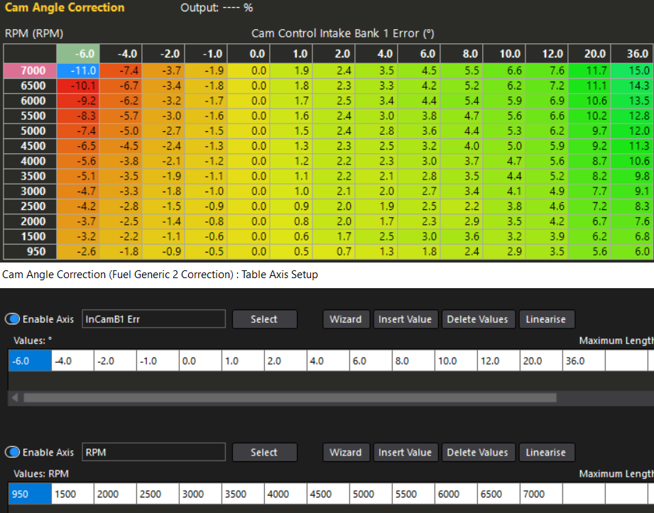
The adjacent screenshot (from Haltech NSP tuning software) shows a custom fuel correction table I've implemented to automatically adjust fueling based on cam angle error. It adds fuel when cam angle increases beyond target, and reduces fuel when cam angle falls below target.
The cam angle naturally deviates slightly from target under different driving conditions. This correction table is enabled by checking the "generic correction" box, then naming it as desired. Configure the axes as follows:
- Y-axis: RPM
- X-axis: Cam Control Intake Bank 1 Error
- X-axis range: -6° to +36° (as shown in the example)
Why use this? Perfectly tuning PID values for cam control is challenging due to varying oil temperature and oil pressure across the RPM range. This table provides a practical workaround. For even better results, install an oil temperature sensor and retune all cam PID tables to reference oil temp instead of coolant temp (see oil temperature sensor benefits section for variable valve timing engines).
• Automatically trims fueling based on live cam angle error
• Helps maintain accurate AFR when cam deviates from target (common during normal operation)
• Typical deviation is ~1°, but larger errors are corrected to prevent lean/rich conditions
• Protection: Guards against solenoid failure or loose electrical connector
• Recommended axes: RPM (Y) × Cam Control Intake Bank 1 Error (X, -6° to +36°)
• Enable via "generic correction" → name table → set axes
Downside: After a shift, cam angle can change rapidly → brief rich condition (~0.5 seconds) as ECU adjusts fueling while engine is off-throttle/down-revving.
Protection benefits: Maintains proper AFR even if the VVT solenoid fails or the connector comes loose. During everyday driving, small cam angle errors (often ~1°) would otherwise cause minor AFR swings — this table keeps fueling on target.
Only real downside: During/after shift events, the rapid cam angle change can cause the ECU to command extra fuel momentarily. Since the engine is typically off-throttle and not demanding fuel during the down-rev, this results in a brief rich spike for about half a second.
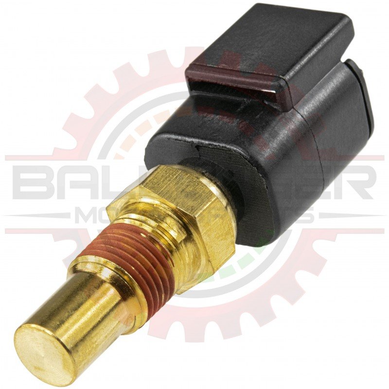
oil temp sensor needed to refine P.I.D.!
Many engine management systems (such as Haltech basemaps) default to adjusting P.I.D. tables based on coolant temperature because most setups lack a dedicated oil temperature sensor. However, coolant heats up significantly faster than oil, which creates challenges when fine-tuning camshaft control (VVT/VCT) or other temperature-based parameters.
Even if your P.I.D. values are dialed in perfectly on a given day, cooler ambient/weather conditions the next day will delay oil warm-up. This shift means you'll often need to re-adjust cam P.I.D.s repeatedly. Installing an oil temperature sensor solves this by providing accurate oil temp data for logging and control — allowing you to determine if your setup needs additions like a thermostatic plate or oil cooler.
If you install an oil temp sensor, refer to the temperature sensors section of this website (or your ECU manufacturer's guide) for proper wiring and ECU configuration. Most common aftermarket oil temp sensors are NTC thermistors (2-wire) and work with a 1k pullup (recommended for Haltech AVIs) or sometimes 2.2k — match your ECU's setting and verify against the sensor datasheet.
1k ohm pullup resistors are standard for faster ECU response (though the real-world difference is usually negligible). Always input the correct volts vs. temperature values into your ECU calibration table for accurate readings.
• Use oil temp (not coolant) for precise P.I.D. control of cam timing / VVT — avoids re-tuning due to delayed oil warm-up
• Common aftermarket sensors: 1/8 NPT thread (check your fitment — some use 1/8 BSPT or M10x1)
• Wiring: 2-wire NTC thermistor → connect with pullup enabled (typically 1k in Haltech)
• Calibration: Input exact volts vs. °C/°F from sensor datasheet into ECU table
• Benefits: Log real oil temps on track → decide on oil cooler / thermostatic needs
• Pullup choice: Match ECU setting (1k or 2.2k) — wrong scaling causes inaccurate temps → poor idle, fueling, timing, cam control
Recommended sensor: Affordable 2-wire 1/8 NPT NTC can be purchased from here or the m10x1 version here. — confirm thread compatibility with your setup.