common fuel sender data
| Vehicle | R_full (Ω) | R_empty (Ω) | Volts Full (1kΩ Pull-up) | Volts Empty (1kΩ Pull-up) | # of Senders |
|---|---|---|---|---|---|
| Audi S4 (2000–2020) | 56 | 285 | 0.27V | 1.11V | 2 |
| BMW 335i (2006–2013) | 410 | 60 | 1.45V | 0.28V | 2 |
| Chevrolet Camaro (1999–2020) | 33 | 240 | 0.16V | 0.97V | 1 |
| Dodge Charger (2006–2020) | 50 | 190 | 0.24V | 0.80V | 2 |
| Ford Mustang (2005–2020) | 15 | 160 | 0.07V | 0.69V | 2 |
| Honda Civic (1992–2020) | 5 | 110 | 0.02V | 0.50V | 1 |
| Infiniti G35 (2003–2008) | 3 | 80 | 0.01V | 0.37V | 2 |
| Lexus IS300 (1998–2005) | 4 (2+2) | 110 (55+55) | 0.02V | 0.50V | 2 |
| Mazda Miata (1989–2020) | 3 | 110 | 0.01V | 0.50V | 1 |
| Mitsubishi Evo 8/9/10 (2003–2015) | 8 (4+4) | 220 (110+110) | 0.04V | 0.90V | 2 |
| Nissan 350Z/370Z (2003–2020) | 6 (3+3) | 160 (80+80) | 0.03V | 0.69V | 2 |
| Subaru WRX (2002–2020) | 13 | 120 | 0.06V | 0.54V | 2 |
| Toyota FR-S (2013–2016) | 9 | 171 | 0.04V | 0.73V | 1 |
| VW GTI (2006–2020) | 350 | 50 | 1.30V | 0.24V | 1 |
The adjacent chart shows most common fuel level sender data as well as other aftermarket brand senders.
These senders are simple resistance-style — basically an arm or float that moves up and down with the fuel level.
Wiring: They will all be 2-wire senders, and sometimes there are two that are connected in series. You'll need to consult your manufacturer's repair manual or wire diagram to mimic or tap into the factory wiring.
Pull-up resistor: You'll need to wire a pull-up resistor in to receive a good signal from the fuel sender unless you have a software-selectable pull-up — in which case you can enable it in your tuning software.
Voltages: The voltages on the adjacent chart should be verified, but they're likely correct.
• Simple variable resistor (float/arm style)
• 2-wire senders (sometimes two in series)
• Pull-up resistor required unless ECU has software-selectable pull-up
• Verify voltages against your specific sender datasheet
• Consult factory wiring diagram for proper integration
Input exact volts vs. fuel level % (or liters/gallons) into ECU calibration table for accurate gauge/readings.
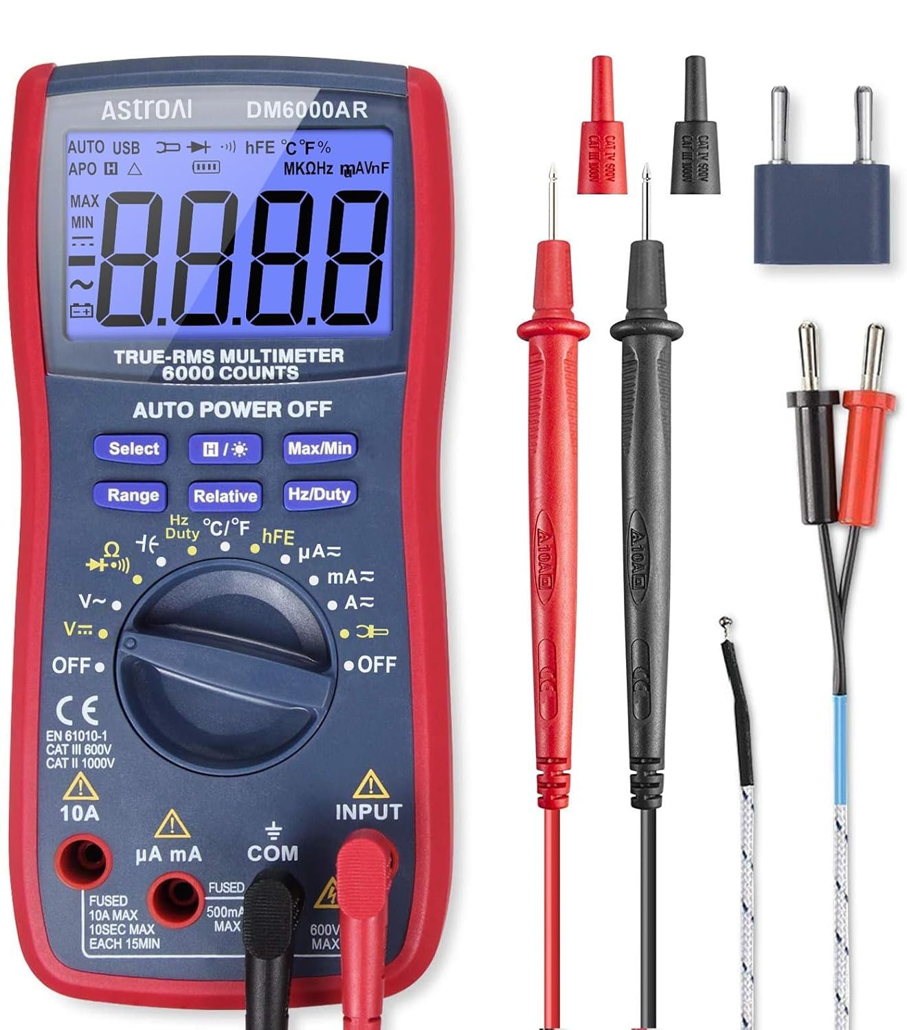
AstroAI Digital Multimeter and Analyzer TRMS 6000 Counts Volt Meter Ohmmeter Auto-Ranging Tester; Accurately Measures Voltage Current Resistance Diodes Continuity Duty-Cycle Capacitance Temperature
Buy on Amazon As an Amazon Associate I earn from qualifying purchases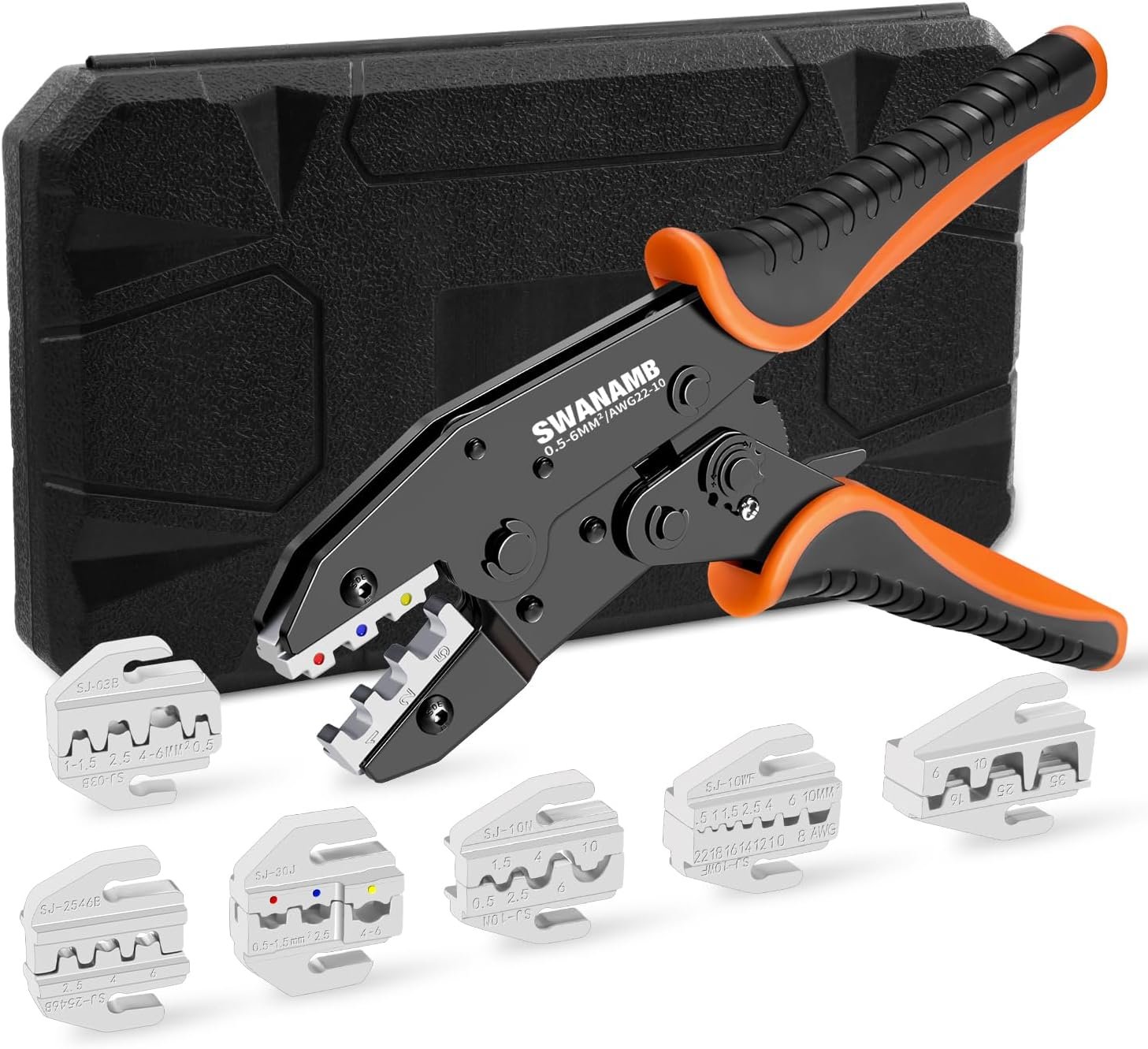
8Pcs Crimping Tool Kit for Heat Shrink Terminals, Non-Insulated, Open Barrel, Solar Conncetors, Insulated and Non-Insulated Ferrules
Buy on Amazon As an Amazon Associate I earn from qualifying purchases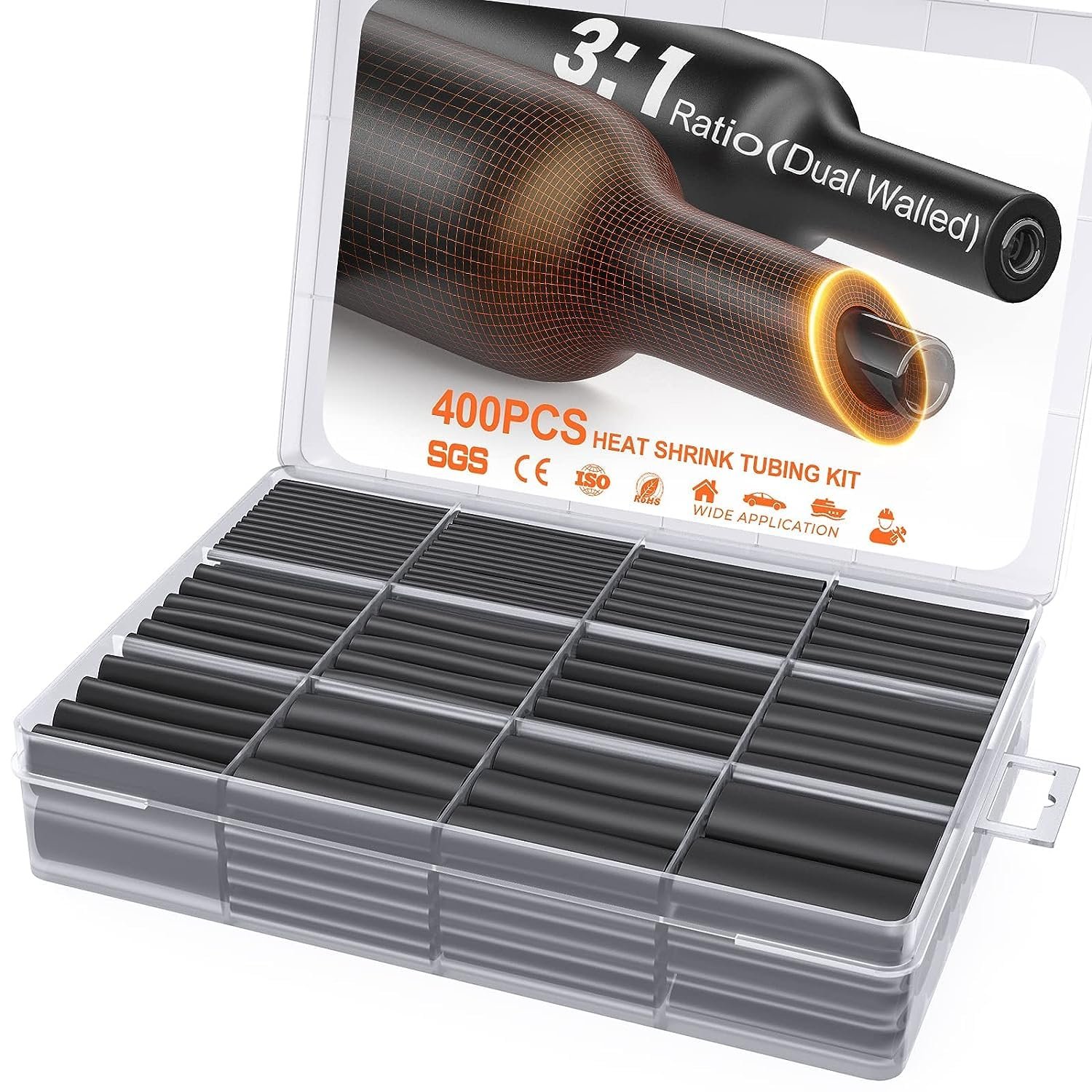
400 Pcs Heat Shrink Tubing Kit-3:1 Ratio Adhesive Lined,Marine Grade Shrink Wrap - Industrial Heat-Shrink Tubing - Black
Buy on Amazon As an Amazon Associate I earn from qualifying purchases
SVAAR 380PCS Non Insulated Butt Connectors Kit Butt Splice Connector Uninsulated Wire Splice Connectors for 26 to 6 Gauge Wire Marine Grade Tinned Copper Seamless Barrel Crimp Butt Splice Terminals
Buy on Amazon As an Amazon Associate I earn from qualifying purchases
3M Scotch Super 33+ Vinyl Electrical Tape, .75-Inch by 66-Feet
Buy on Amazon As an Amazon Associate I earn from qualifying purchases
AstroAI Digital Multimeter and Analyzer TRMS 6000 Counts Volt Meter Ohmmeter Auto-Ranging Tester; Accurately Measures Voltage Current Resistance Diodes Continuity Duty-Cycle Capacitance Temperature
Buy on Amazon As an Amazon Associate I earn from qualifying purchases
8Pcs Crimping Tool Kit for Heat Shrink Terminals, Non-Insulated, Open Barrel, Solar Conncetors, Insulated and Non-Insulated Ferrules
Buy on Amazon As an Amazon Associate I earn from qualifying purchases
400 Pcs Heat Shrink Tubing Kit-3:1 Ratio Adhesive Lined,Marine Grade Shrink Wrap - Industrial Heat-Shrink Tubing - Black
Buy on Amazon As an Amazon Associate I earn from qualifying purchases
SVAAR 380PCS Non Insulated Butt Connectors Kit Butt Splice Connector Uninsulated Wire Splice Connectors for 26 to 6 Gauge Wire Marine Grade Tinned Copper Seamless Barrel Crimp Butt Splice Terminals
Buy on Amazon As an Amazon Associate I earn from qualifying purchases
3M Scotch Super 33+ Vinyl Electrical Tape, .75-Inch by 66-Feet
Buy on Amazon As an Amazon Associate I earn from qualifying purchasesfuel sender configuration
The adjacent chart shows typical fuel level sender data as well as common aftermarket and OEM sender characteristics.
This information should be used as a starting point — always verify against your specific fuel sender's resistance range and your vehicle's tank geometry.
It's important to calibrate the voltage-to-level relationship accurately in your engine management system for reliable fuel level display and low-fuel warnings.
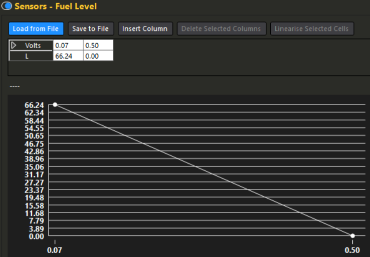
• Enable "Fuel Level" option under Sensors menu in Haltech NSP
• Use measured voltages from empty → full as primary calibration points
• Best method: record voltage at near-empty (e.g. after adding 5–6 L to dry tank), then at full
• Input exact volts vs. liters/%/gauge position into ECU calibration table
• Gauge control output requires creative setup — CAN gauges usually cannot be driven directly by Haltech
• For analog gauges: use a Generic Output → Frequency signal type → Table mode → experiment with duty cycle values (start ~50%) for empty, ¼, ½, ¾, full
• Always double-check: Incorrect calibration → inaccurate fuel level reading → risk of running out of fuel or false warnings
Measure real voltages on your vehicle whenever possible — sender resistance curves vary significantly between models and manufacturers.
Fuel level warning light
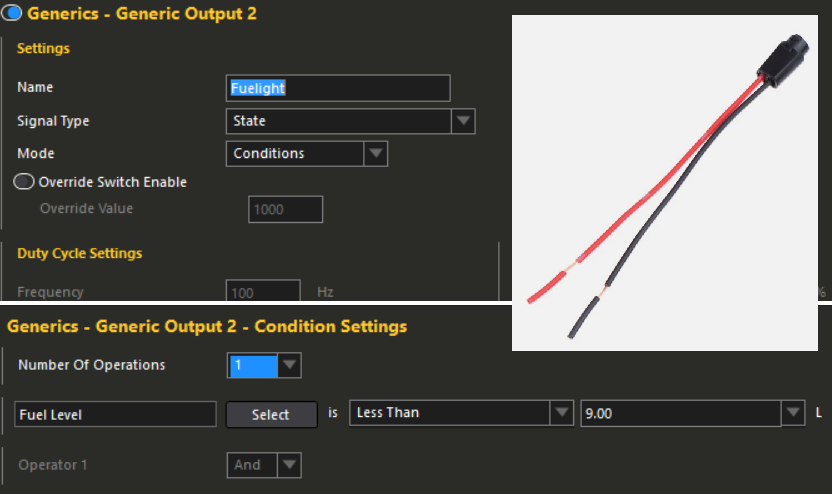
In the case of a low fuel level, if you have an available generic output on a Haltech ECU, you can wire it to the negative side of a bulb in your cluster. If your bulb is wired internally (most are), you can buy a pigtail like the one shown in the adjacent picture. The pigtail holds a T5 bulb (for my IS300 gauge cluster). A set of 4 was less than $10 on eBay.
If your gauge is like mine (pre-00's era toyota) and your haltech cannot control it since it uses the BEAN control network, use a bulb
Wiring: Connect the Haltech generic output wire to the ground side of the bulb. Connect the other side of the bulb to a fused ignition-switched positive source.
Configuration: Use the settings shown in the adjacent picture to trigger the fuel warning light bulb. This creates a generic condition that activates the light when the fuel level reaches 9 L or less.
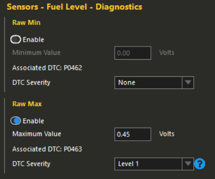
Use a CEL/DTC as a fuel level warning
As far as known, this can only be implemented natively in a Haltech ECU, as they are the only ECUs with built-in OBD2-style DTC support for triggering a check engine light based on fuel level sensor voltage.
This will trigger a Check Engine Light (CEL) if your fuel level drops below a certain voltage threshold on the sensor.
Configuration: Set your diagnostic settings as shown in the adjacent picture.
Requirements: Your check-engine-light must be operational on the gauge cluster and properly wired to the Haltech ECU output for this feature to function.
Things to consider:
- If your sensor voltage rises as the fuel level drops (like most common senders): set the "Raw Max" value to be below your maximum sensor voltage.
- If your sensor voltage drops as the fuel level drops (less common direct-type sender): set the "Raw Min" value to be above your minimum sensor voltage.
- Always verify your specific fuel level sensor behavior using live data or a multimeter before applying settings.