Basic automotive relay components
Basic Automotive Relay Anatomy (4-Pin & 5-Pin Bosch Style)
A basic automotive 4-pin or 5-pin relay is composed of two halves:
- One half is a basic electromagnet that will be powered by 12 volts in almost all situations.
One of these connections is 12V power, the other is ground.
In a Bosch-style relay, the 12V connection to the coil is numbered 86, and the ground for the coil is numbered 85. - The other half is a simple switch that makes an electrical connection when the electromagnet pulls a gate shut.
In the Bosch style relay:
• The "input" (power in) is numbered 30
• The N.O. (normally open) connection (output when relay is energized) is numbered 87
A 5-pin relay adds pin 87a, which is also known as the N.C. (normally closed) position. This pin is connected to pin 30 when the relay is not energized (coil off).
Note: If you ignore pin 87a on a Bosch 5-pin relay, you'll have a fully functional 4-pin relay — just leave 87a unconnected.
For a animated walkthrough of how relays work, check out my YouTube Video here.
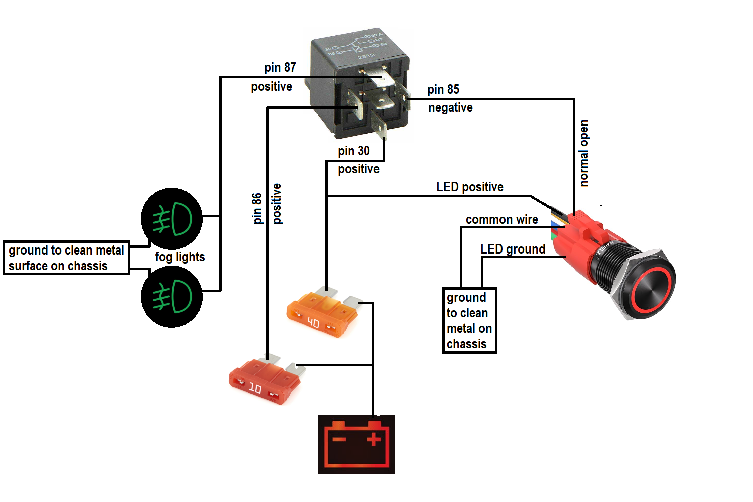
• 85 → Coil ground (trigger side)
• 86 → Coil +12V (trigger side)
• 30 → Power input (fused +12V from battery/source)
• 87 → Normally Open output (to load: pump/fan/lights/etc.)
• 87a → Normally Closed output (only on 5-pin — connected to 30 when coil is off)
4-pin = basic on/off switching
5-pin = adds optional "off-position" circuit (most common in automotive use)
Relay Coil Diode & 4 or 5-Pin Wiring Options
Going into a little more detail, the electromagnetic coil that's connected to pins 85 and 86 on Bosch-style relays may also come with a device called a diode between pins 85 and 86.
This means that you can only connect:
- Pin 85 to a ground source
- Pin 86 to a power source
Cheaper relays will not have this diode inside, so pin 86 or 85 can be used as ground, and the remaining of the two pins can be used as power — polarity doesn't matter in that case.
Sometimes a 5-pin relay is needed in order to give the user the option to have the relay make a connection when it is not being powered between pins 30 and 87a (normally closed position).
The relay can also be wired in "reverse" so:
- Pin 87 is the input (power in)
- Pin 30 powers a device (output when energized)
Or you can use two separate power sources (one on 87a and another on 87), and each can power a device via pin 30 — switching between them depending on whether the coil is energized or not.
I go over some advanced examples on the other page here.
• Diode-equipped (most quality Bosch-style): 85 = ground, 86 = +12V only (protects from voltage spikes)
• No diode (cheap relays): 85/86 reversible — polarity doesn't matter
• 5-pin advantage: Use 87a for "off" state connection (NC)
• Reverse wiring: 87 in → 30 out (energized state)
• Dual-source switching: 87a + 87 both feeding 30 → select source based on coil state
Diode relays = safer for ECU/switch triggering; 5-pin = more flexible circuits — check your relay specs!